
Enerdrive Unplugged – A Wealth of Knowledge at Your Fingertips:
Before you jump into our explanation of cable risks, theory and best practice, consider joining our community Facebook group – Enerdrive Unplugged. Designed to be an educational tool, you’ll find a wealth of knowledge and a supportive environment to ask questions and get advice from veteran users and our own highly qualified staff!
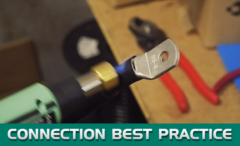
Everything you need to know about cable connections:
Although business connections are a critical aspect of running any successful business, so are those of an electrical nature. Although we could discuss the former, we will focus on the latter. As too often we see poorly designed systems or “she’ll be right!” jobs that cause headaches down the track. We’ll take a look at some of the common mistakes and then discuss best practices.
So, what are the risks of bad connections?
Voltage Drop:
Even the best made connections have resistance and therefore voltage drop. It is for this reason connections must be kept to a minimum. The practice of joining wires when you are 10cm short of the connection is less than ideal. Voltage drop is like a kink in your fuel hose, sure your system will run but the more you put your foot on the accelerator the worse the performance will be until eventually the system cuts out on low fuel delivery. Items such as fridges, inverters and DC2DC chargers all rely on good constant voltage to ensure best performance and are usually the items that will shut off first due to low voltage.
No one likes hot beer and smelly bait.
Heat:
Not only does resistance create voltage drop but this then leads to heat. The most common cause of electrical fires is due to loose, damaged or corroded connections. So now that is in everyone’s mind, there is not much else to say.
I remember when I did my American Boat and Yacht Council (ABYC) certification back in 2003 the instructor was advising the importance of using thermal measuring guns to check connections and cable sizing (a topic for another day). To date, I still find this one of the best test tools to have and now that thermal cameras have become more affordable there is no reason not to carry out these tests when commissioning a new system or fault finding. If this tool is not available to you, then by feeling with your bare hand over each connection will help indicate which connection is poor due to heat buildup on that connection.
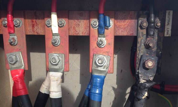
Spot the difference! A loose connection on the main neutral maybe?
Intermittent faults:
That’s right, the ones we all hate to fault find. The owner drives in complaining of something not working over the weekend yet in the workshop everything is working just fine. Loose or corroded connections on electrical or data cables can cause a myriad of random faults to occur and quite often take hours to fault find, especially when it cannot be replicated whilst the vehicle is stationary.
The theory behind it?
OK, stay with me for this bit, it won’t be as bad as algebra at school! The most important principle in the electrical field is Ohm’s Law, which can be visualized in the below formula where V=Volts, I= Current (Amps) and R=Resistance.
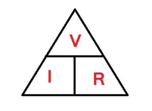
So based on Ohm’s Law let’s see the effect of a bad connection creating resistance.
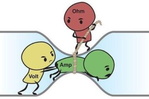
Loose, corroded or otherwise poor connections create a high resistance to electrical current flow. It takes a certain amount of power to force electrons to flow through an area with a given resistance. As you force electrons to flow faster through that area of resistance (i.e., increase the electric current, amps), the power required to do that increases exponentially (I^2) with respect to the current. The power is used locally at the connections and is expressed as heat (remember above) …heat being a measure of the motion of atoms in the area.
Power = Current x Voltage (P=IV)
Voltage = Current x Resistance (V=IR)
Substituting the second formula into the first: P=IxIxR = I^2R
Therefore on a 75 Amp load with a bad connection with just 0.5 Ohm resistance you are creating 2812Watts of power in the form of heat.
The other problem with the bad connections creating resistance is the voltage drop across the connection decreases the supply voltage to the load (inverter, light, pump etc.) which in turn increases the current draw on the system, which then affects the above formula by creating even more heat at the connection.
Now that we know the effects and theory behind it, let’s look at some less than ideal installs from our archives along with best practices.
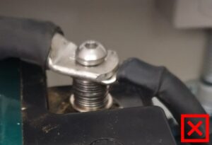
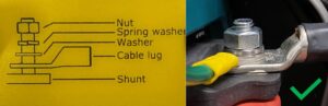
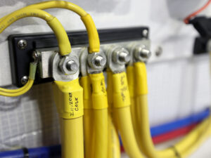
Layering, just like painting, you don’t put the topcoat on first then undercoat. The correct layering/ordering of connections is key especially on battery terminals and busbars. The order should always be the highest current draw items in direct contact with the battery, busbar, or stud. From there work your way through any remaining connections from highest to lowest current draws. If your circuits have been cable sized correctly for the load, then largest cable first to the smallest cable last. Also ensure that the lugs mate directly to each other and to the terminal, no washers, spacers or nuts in between.
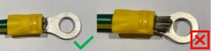
Correct terminal sizing is also key, the practice of cutting excess cable strands to fit in a smaller lug, using an oversized eye terminal or even worse drilling out an undersized eye terminal all show signs of poor workmanship and will lead to increased issues. Lug surface areas are designed based on cable size and terminal size, so modifying any of these aspects will affect the performance.
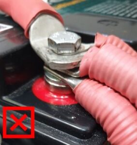
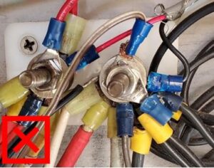
The number of connections per terminal is another consideration. ABYC marine standard E-11 states that no more than 4 connections shall be made to any one terminal stud (battery, stud, busbar). Why is this? Through each lug you are getting resistance, heat and voltage drop, also not to mention on battery terminals you risk not having enough bolt inserting into the battery terminal therefore risk the connection becoming loose or stripping the thread. In situations where you have more than 4, or even three large connections it is recommended to change to a busbar.
Lastly, usually the first process of making a connection, is the lug or crimp terminal itself. Whilst there is much debate around the use of solder, I again follow guidance from ABYC where in marine installations solder shall not be used. Why you may ask? This is not about the electrical performance of the connection but rather the mechanical performance. When the cable is soldered the joint becomes very rigid and where the solder finishes the wire can become susceptible to snapping due to the heating process to melt the solder. You should never use soldered cable with a Compression fitting. As mentioned, because the joint becomes ridged, you will not be able to clamp the Compression fitting down correctly hence making a very poor connection and creating excessive heat and resistance.
So, if you or your customer insist on soldering, keep this in mind and ensure suitable strain relief such as heat shrink and fasteners are used.
So now that we are using crimp terminations what else do we look for. The crimp itself should be selected based on the cable size and termination size as mentioned earlier. Consider using dual wall lugs in place of single wall lugs, this ensures there is a significantly lower chance of the lug snapping, especially in applications like starter motors or alternators where there is a lot of movement.
The crimping method itself should always be done with the correct tool for the job and no, a hole punch and hammer does not equal a crimper. Correct crimpers, such as manual or battery-operated hex crimpers for battery lugs are commonly preferred over indent crimpers. With the smaller insulated (red, blue, yellow) terminals, ensure you are using a crimper that crimps the conductor and insulation, not just a single crimp. The wire should protrude just slightly through the crimp, however not enough to interfere with the mating surfaces.
All other crimps such as Deutsch, QK, & Ferrules should be made using dedicated crimpers. Consider the use of glue filled crimps where water or moisture may enter the cables, the green wire cable can be one of the harder faults to find!
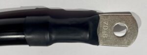
Heat shrink. It is an insulator and when used correctly shows a high level of workmanship. When not used correctly it can be the opposite and show very low level of workmanship! Remember, it is an insulator, so always ensure it is not overhanging onto the conducting surface of the lug. Also consider glue filled heat shrink (dual wall as sometimes known as) in marine applications especially in wet areas.
Last tip, if you really want to go the extra mile and up your game, consider using a visual indicator that the connection has been tightened correctly. This can make fault finding easier, don’t however use Loctite.
Well, after all this I trust you are all well connected now. Next topic will be closely connected to this one…you guessed it, cable!
Author: Greig Payne
* Licensed Electrical Contractor (Qld #75357)
* Participating member for AS/NZS 3004 (EL-057) Standards Committee
* Participating member for AS/NZS 3001 (EL-001-17-02) Standards Committee
* American Boat and Yacht Council (ABYC) Certified Marine Electrical Technician
* Certificate III in Electrotechnology

