How to: Connecting Batteries in Parallel, Series, or Both
There are several things to consider when connecting batteries in parallel or in series to achieve the correct battery voltage or capacity for a particular DC installation. By connecting batteries in series or parallel or both as one big bank, rather than having individual banks will make your power source more efficient and will ensue maximum service life for your battery bank.
Connecting Batteries in Series
Wiring batteries together in series will increase the voltage while keeping the amp hour capacity the same.
For example;
- 2 x 6V 120Ah batteries wired in series will give you 12V, but only 120Ah capacity.
- 2 x 12V 120Ah batteries wired in series will give you 24V, but still only 120Ah.
Connecting Batteries in Parallel
Wiring batteries together in parallel has the effect of doubling capacity while keeping the voltage the same.
For example;
- 2 x 12V 120Ah batteries wired in parallel will give you only 12V, but increases capacity to 240Ah.
Connecting Batteries in Series/Parallel
This is a combination of the above methods and is used for 2V, 6V or 12V batteries to achieve both a higher system voltage and capacity.
For example;
- 4 x 6V 120Ah batteries wired in series/parallel will give you 12V at 240Ah.
- 4 x 12V 120Ah batteries can be wired in series /parallel to give you 24V with 240Ah capacity.


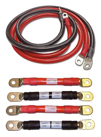
Battery Cable Connections
The cables that join your batteries together play an important part in the performance of your battery bank. Choosing the correct size (diameter) and length of cable is important for overall efficiency. Cables that are too small or unnecessarily long will result in power loss and increased resistance.
When connecting batteries in series or parallel or series/parallel the cables between each battery should be of equal length. As you can see in the diagrams above, all the short cables connecting the batteries together are the same length and all the long cables are the same length. This links the batteries together with the same amount of cable resistance, ensuring that all batteries in the system are working equally together.
Particular attention should also be paid to where the main system cables are connected to the battery bank. More often than not, the system cables supplying the loads are connected to the first or “easiest” battery to get to in the bank, resulting in poor performance and service life. These main system cables that run to your DC distribution (loads) should be connected across the whole bank as illustrated in the diagrams above. This ensures the whole battery bank is charged and discharged equally, providing optimal performance.
The main system cables and the cables joining the batteries together should be of sufficient size (diameter) to handle the total system current. If you have a large battery charger or inverter you want to make sure that the cables are capable of carrying the potentially large currents that are generated or consumed by these pieces of equipment, as well as all your other loads.
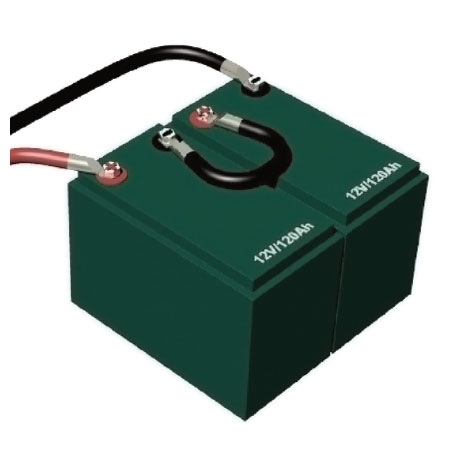
Series Connection
Batteries are coupled in series to gain higher voltage, for instance 24 or even 48 Volt. The plus pole of each battery is connected to the minus pole of the following one, with the minus pole of the first battery and plus pole of the last battery connected to the system. This type of arrangement shown is a 24v, 120Ah bank.
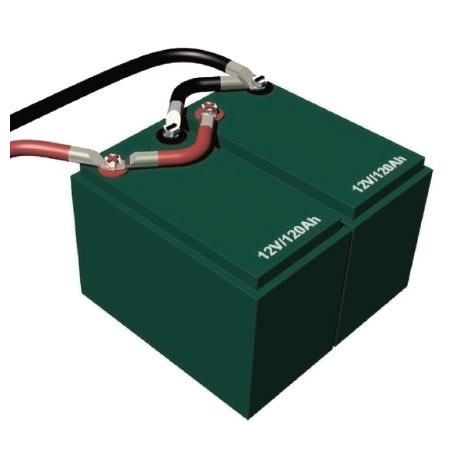
Parallel Connection
Parallel coupling involves connecting the plus poles of multiple batteries to each other and the same with the minus poles. The plus of the first battery and the minus of the last battery are then connected to the system. This type of arrangement is used to increase capacity (in this case 12v 240Ah).
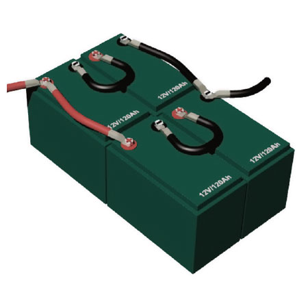
Series/Parallel Connection
A combination of series and parallel connections is required if you need for example a 24 Volt battery set with a higher capacity. The battery should then be cross-wired to the system using the plus pole of the first and minus pole of the last battery. This type of arrangement shown is a 24v, 240Ah bank.
Cable Sizing
In an independent power system, you generally would find an inverter and battery charger system working for the common goal of providing power. What ties each of these together are the cables to supply the power to run to or from the batteries or DC distribution. Unfortunately, the most common installation error is to under-size cables to the load/s or from the recharge sources.
Proper installation is primarily a matter of sizing a cable to match its task, using the correct tools to attach terminals, and providing adequate over-current protection with fuses and circuit breakers.
Cable sizing is simple enough. It is a function of the length of a cable (measuring from the power source to the appliance and back), and the current (amperage) that will flow through it. This can be found by checking the label on the appliance in the circuit, or the specifications sheet for the appliance. The longer the cable, or the higher the amperage, the bigger the cable must be to avoid unacceptable voltage losses. And there should always be plenty of extra margin for safety because an appliance may actually use more current than what it is rated for because of heat, low voltage, extra load and other factors.
For 12V circuits, the relationship between cable length, current flow, and cable size is given in the table below. Note that you have two circuit types, Critical & Non Critical. The “critical” circuit is based on a 3% voltage loss in the cable, while the “non-critical” circuit is based on a 10% voltage loss. What this means is that when the circuit is fully loaded (i.e. operating at rated amperage), the voltage at the appliance will be 3% or 10% below that at the battery. For example, if the battery is at 12.6 volts, the appliance will be seeing 12.2 volts (3% loss), or 11.34 volts (10% loss).
Many appliances (notably lights) will run fine with a 10% voltage loss, but others are particularly sensitive to such losses (notably charging & inverter circuits, and some electric motors). In general, given the harsh realities of the RV & marine environment, it’s better to use the 3% volt drop table when sizing cables, rather than the 10% table. There’s never a performance penalty if a cable is marginally oversized; there is always a performance penalty (and possibly a safety hazard) if it’s undersized.
The ground (negative) cable is as much a part of a circuit as the positive cable; it must be sized the same. In general, each appliance should be supplied from the distribution panel with its own positive and negative cables, although lighting circuits sometimes use common supply and ground cables to feed a number of lights (in which case the supply cables must be sized for the total load of all the lights).
For 24v systems, the cables size is half that of a 12v setup.
Always read product recommendations, or check with your supplier to know and understand exactly what size cable is required for your products.
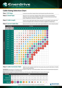
Enerdrive Cable Chart The cable sizing table is used by running across the top row until the column with the relevant amperage is found, and then moving down the left-hand column until the row with the relevant distance is reached. The colour coding in the body of the table at the intersection of this row and column is the wire size. Compare this with the Cable Conversion Table to see what size cable to use.
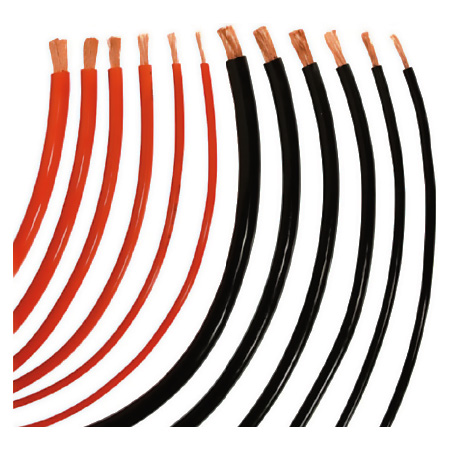
The AWG (American Wire Gauge) is used as a standard method of denoting wire diameter, measuring the diameter of the conductor (the bare wire) with the insulation removed. AWG is sometimes also known as Brown and Sharpe (B&S) Wire Gauge. Most Australian Auto Electricians use the B&S scale.
Also listed is a conversion chart from AWG/B&S to mm². This table gives the closest equivalent size cross references between metric and American wire sizes. In Europe and Australia, wire sizes are expressed in cross sectional area in mm².
Other important points to bear in mind when wiring boats or RV’s:
- All circuits should be as high as possible with no connections in or near bilge water or damp areas.
- All cable lug connections should be well crimped and NOT soldered
- It is preferable to use tinned cable where possible in a marine environment
- Use twisted-pair cable for any wiring within 1m of a compass.
- Never tap into existing circuits when installing new equipment; run a properly-sized new duplex cable (positive and negative cable in a common sheath) from the distribution panel (or a source of power) to the appliance.
- It is recommended to label all cables at both ends, and you should keep an updated wiring plan on board, to aid in future troubleshooting.
- Each circuit should have an independent ground cable, and all the ground cables should eventually be tied back to a common ground point/bus bar which is grounded to the battery negative; if devastating stray current is to be avoided, this is the only point at which the grounds should be interconnected.
- Unless in a conduit, cables should be supported at least every 450mm.
- Although black is often used for DC negative, it is also used for the live wire in AC circuits in the USA. That means there is potential for dangerous confusion. DC and AC wiring should be kept separate; if they have to be run in the same bundle, one or the other should be in a sheath to maintain separation and ensure safety.
- Be sure to isolate the batteries before working on the DC system, and, for safety sake, shut off all potential AC power sources (the shore power, and on-board AC generator, or an inverter).

